Civil works and steel structures are the part of a project where mistakes get expensive and hard to undo. A badly fed panel can be redone over a weekend; anchor bolts cast out of position stop the entire erection sequence and force you to demolish and pour again. At De La Mar we execute foundations and civil works, fabrication and erection of steel structures, rigging and lifting operations, and field welding, both in new construction and in expansions inside facilities that keep producing. What follows explains how that work is executed and what is worth reviewing before you contract it.
Foundations and civil works
The foundation is not decided by the building: it is decided by the soil. The geotechnical study determines bearing capacity and allowable settlement, and from there comes the type of solution: isolated footings under each column, tie beams, a mat foundation, or piles when the competent stratum lies deep. Skipping that study to save a few weeks is the most common way to turn a small saving into a large structural problem.
Typical scope covers layout and leveling, excavation, blinding, rebar and pouring of pedestals and tie beams, compacted fills, industrial slabs and floors, manholes, trenches, sumps, and retaining walls. On projects with an electrical load, it also includes the civil work that supports the installation: transformer pads, duct banks, cable trenches, and switchboard plinths, all of which are better resolved alongside the structure rather than afterwards, once the floor has already been poured.
Within all of this there is one item that deserves disproportionate attention: the anchors. The position of each column’s anchor bolts is set with a template and verified before the pour, because the tolerance they arrive with decides whether the base plates seat properly or whether you rectify in the field with the crane waiting and the whole crew standing still. It is a check that takes hours and saves weeks.
Steel structure: from shop to erection
The steel weight of an industrial building depends far less on its floor area than on its clear span, and not in a linear way. The bending moment a truss or a frame must resist grows with the square of the span, so increasing the distance between supports means increasing the section; the larger section weighs more, and that added weight loads the structure again. Doubling the span does not double the steel: it multiplies it by considerably more. That is why the question that moves the budget most is not technical but operational: how many intermediate columns can the operation tolerate? A forklift aisle, a production layout, or a maneuvering yard may justify a long clear span; a warehouse that does not need one is paying for steel it will never use. That decision belongs to the client, made with information, not to the structural engineer working alone.
Before a single plate is cut, detailing and shop drawings are produced. It is the stage most often underestimated and the one that saves the most money: a change caught on the drawing is resolved with an email; the same change with the steel already cut is wasted material. Once drawings are approved, shop fabrication —cutting, fitting, assembly, welding, surface preparation, and primer— runs in parallel with the foundation work. That parallelism is what actually structures the project schedule.
Erection is deceptive. It is the visible phase, the one that gets photographed and the one that makes everyone think the job is nearly done, because the frame goes up in a matter of days. But it is not the longest phase: behind it are weeks of fabrication nobody saw, and ahead of it remain pluming, final bolt torque, field welds, permanent bracing, roofing, and detail work. A schedule that treats erection as the bulk of the job will be wrong in both directions.
Rigging and lifting
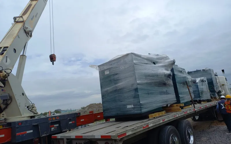
Two identical structures can cost different amounts for one reason alone: how the crane gets there. A crane is not selected by the weight of the piece, but by the combination of weight, working radius, and hook height. Its capacity drops quickly as it moves away from the center of rotation. If the yard lets you bring it close to the erection point, a modest machine will do. If a production line, a perimeter wall, or an overhead power line forces it to work from a distance, you need a larger crane, with more counterweight, more assembly time, and access roads that sometimes have to be built. The structure is the same; the cost and the schedule are not.
That is why every significant lift is executed with a written lift plan: the real weight of the piece —including fittings, slings, and rigging gear, not the nominal weight on the drawing—, the center of gravity, the lifting points, the crane’s load chart for the planned radius and boom configuration, ground bearing capacity under the outriggers with their spreader pads, the exclusion zone beneath the load, tag lines, and the wind speed at which work stops. The plan also fixes the sequence: what goes up first and what stays temporarily braced, because a half-erected frame is not stable on its own until the bracing is in place.
Welding and critical connections
A bad weld in a critical connection is invisible. From the outside you see a bead; lack of fusion, incomplete penetration, internal porosity, or a crater crack are not visible. And the connection does not fail on the day it is welded: it fails later, under load, under wind, under seismic action. That is why the procedure is defined before work begins and never improvised in the field: process and filler material, edge preparation, preheat where the thickness calls for it, number of passes, and cleaning between them. We work with qualified welders and a defined procedure, keeping a record of which welder executed which connection.
Inspection is graded according to the structural responsibility of the connection, because not all of them carry the same load. A fillet weld on a secondary purlin is verified visually: throat size, length, continuity, undercut, slag. A complete penetration weld on a moment connection, a column splice, or any member whose failure would compromise global stability calls for non-destructive testing —ultrasonic or magnetic particle, depending on the case. Defining that inspection map from the design stage, stating which connections are tested and by what method, avoids an expensive argument at the end of the job. It is also worth designing to minimize field welding: welding at height, in wind, in a forced position and with limited access is never equivalent to welding in the shop, and wherever a bolted connection will do, it usually should.
Safety on site
In steel erection, safety is not an appendix to the file: it is the working condition itself. NOM-009-STPS applies to work at height, meaning above 1.80 m, and an erector spends the entire shift above that threshold. It requires a risk analysis before the activity, fall protection systems —collective measures first, such as guardrails and nets, then personal ones: full-body harness, lifeline, and anchor points with verified capacity—, work authorization, and personnel who are trained and medically fit for the task.
NOM-031-STPS covers safety and health conditions on construction sites: a designated safety officer, risk analysis by project stage, preventive services, delimitation and signage of work areas, control of machinery and equipment, and housekeeping. That last item sounds minor and is not. A disorderly site is an unsafe site, and it is also a slow one: material that cannot be found, scaffolding in the way, and a blocked crane route are all paid for in rework and in crew hours standing idle.
If you have a project still being defined —a new building, an expansion, a mezzanine, platforms, or reinforcement work— the time to review spans, loads, and crane access is before the executive design, not after. That is when the decisions are still cheap.