An industrial network almost never fails on the day it is installed. It fails two years later: when a production line has to be moved and nobody knows where the cable leaving the patch panel goes, when a new device is added to the site and there is no room left in the cable tray, or when a link that always worked starts dropping packets and there is not a single measurement to compare it against. Structured cabling is one of those line items that gets judged too late: as long as everything links up, any installation looks fine. What we deliver is not just a network that comes online, but an infrastructure that stays diagnosable, measurable and expandable long after we have left the site. That is decided in the pathways, in the terminations, in the certification and in the documentation, well before the network carries its first packet.
Pathways: the part nobody sees
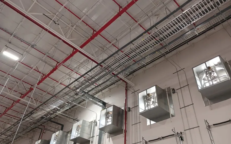
Pathways —cable trays, conduit, pull boxes, supports— are what holds everything else up, and the only part that cannot be redone later without going back into the plant. Two decisions define them: spare capacity and separation.
Spare capacity is easy to explain and easy to ignore when there is pressure to close the budget. A tray handed over at one hundred percent fill is a tray that will force a new run the first time the plant grows, and that new run will be built with the plant in operation, with scaffolding between lines and with work-at-height permits. Sizing with headroom is cheaper than doing it twice.
Separation is a matter of physics. A power conductor and a twisted pair do not need to touch in order to couple: the field generated by current in the first induces voltage in the second. The twisted pair defends itself through geometry —because of the twist, both conductors pick up nearly identical noise and the differential receiver cancels it— but that rejection has a limit, and a long parallel run alongside a power feeder exhausts it. That is why data cabling runs separated from electrical cabling, and why, when a crossing is unavoidable, it is made at a right angle, the geometry that minimizes coupling. It is also why we respect bend radii: bending a cable past its minimum radius deforms the twist, alters the impedance of the pair and produces return loss at precisely the point where the installer pulled too hard.
Cabling and link certification
Certification is not paperwork at the end of the job: it is the only proof that what was bought is what got installed.
A badly terminated link almost always passes the easy test. If the wire map is correct, the link comes up, answers a ping and carries light traffic without complaint. The problem shows up under load, with high temperature above the ceiling, or when the link is asked for a higher data rate than it saw on commissioning day. The causes are usually mechanical and microscopic: too much untwist at the connector, badly applied pressure on the punch-down tool, a poor-quality patch cord.
A link certifier measures exactly what a ping cannot see: wire map and continuity, length, insertion loss, near-end and far-end crosstalk, return loss, propagation delay and delay skew between pairs. It then compares every value against the limits of the category that was contracted, and issues a pass or fail. Without that report, saying “category X cabling” is a statement about the box the cable came in, not about the installed link: the category is delivered by the finished assembly —cable, connectors, cords and workmanship— not by the reel. A link that barely passes, with minimal margin, is a link that works today and does not work tomorrow.
It is also worth understanding why a normative distance limit exists for the horizontal copper link. Attenuation grows with length and with frequency, so beyond a certain distance the signal no longer arrives with enough margin for the bandwidth the category promises. That distance budget is also shared between the permanent run and the patch cords at both ends: this is why the fixed run must be planned shorter than the total link, and why the location of telecommunications cabinets is decided on the drawing and not in the field.
Copper and fiber
The choice between copper and fiber comes down to three criteria: distance, bandwidth and interference. In an industrial environment, the third one usually decides.
Copper remains the right answer for most horizontal outlets: it is cheaper, it is what end devices expect, and it lets a single cable power cameras, access points, phones and controllers. Fiber solves what copper cannot: distances beyond what the horizontal link allows, backbone between buildings, and aggregation bandwidth.
And it solves a problem that is decisive inside a plant. Fiber carries light through a dielectric medium: there is nothing in it to induce, it forms no ground loops, and it couples no noise from the power cables running beside it. A variable frequency drive switches its output voltage at high frequency with very fast edges; that switching radiates energy and conducts common-mode noise along the motor cabling. A copper link sharing a route with the output of a drive is in the worst possible place in the plant. If the route is unavoidable —and in a manufacturing hall it often is— fiber stops being a luxury and becomes the correct engineering answer, the one that avoids coming back six months later to chase intermittent errors that only appear when the motor starts. It is also the answer when a link crosses between buildings with different ground references, where a metallic cable is a path for currents nobody invited.
The site: racking, order and documentation
The site is where everything above is collected. A well-built cabinet has a deliberate layout, cord management, defined routes for cable entry and exit, respect for the minimum bend radius of fiber, airflow consistent with the equipment installed in it, proper grounding, and free space to grow.
Labeling is not cosmetic. It is the difference between finding a port in five minutes and finding it over an afternoon, with the plant stopped and management waiting. We label at both ends, with a consistent scheme, and we hand over as-built drawings, a rack diagram, a link schedule and the certification results tied to each identifier. An undocumented site works right up until it doesn’t; on the day of the incident it becomes an archaeology exercise, and that exercise is paid for in downtime hours. Documentation is the first thing sacrificed when there is a rush and the first thing missed when something goes down.
Growing on an existing installation
Most projects do not start from scratch. We arrive at a site that already carries ten years of accumulated decisions, some of them good and some of them made in a hurry.
The first step there is an honest survey: what pathways exist and how much spare capacity is left in them, which links are certified and which never were, what is labeled and what is a mystery. With that on the table, the recommendation is often not to add but to put things in order first. Dropping twenty new links into a cabinet with no cord management and no labeling does not create twenty links: it creates twenty future problems and raises the cost of every later intervention, ours or anyone else’s. Tidying up before growing almost always costs less than growing on top of the mess and paying the surcharge on every maintenance visit.
Growth is executed in stages, in windows agreed with operations, without taking down the services the plant needs in order to produce. And because De La Mar also performs the civil works and the electrical installation, the pathways, the supports, the wall penetrations and the coordination with power loads are resolved inside the same team, instead of being negotiated between contractors who point at each other when something does not line up.